
6 min read

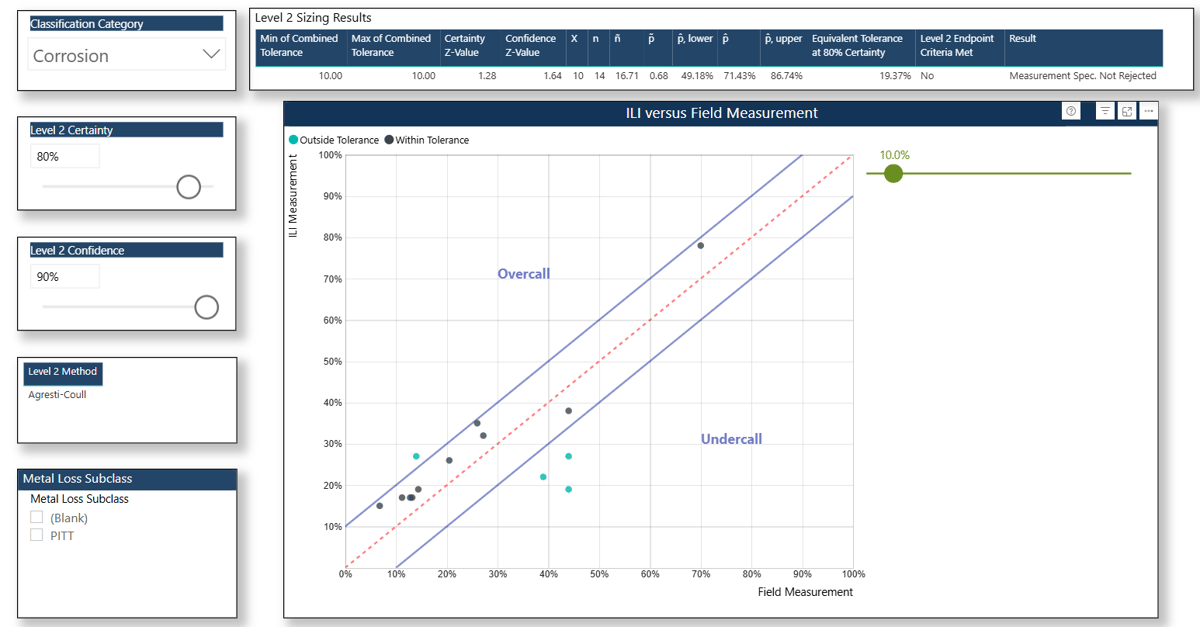
Our State of Integrity report, presented at this year's PPIM conference, discussed how ILI service providers are not meeting their published performance specifications. As shown in the figure below, when the tolerance is +/- 10% and the certainty is 80% (common performance specifications for predicting the depth of metal loss for both ultrasonic and magnetic flux leakage systems), only one ILI provider out of 21 meets or exceeds this specification. With the publication of the third edition of API 1163 In-line Inspection Systems Qualification, pipeline operators now face clearer (and more stringent) requirements. With the publication of PRCI's guidance document and associated spreadsheet tool, meeting these requirements is easier than ever.
Let’s delve into what’s changed in the 3rd edition (versus the 2nd), why it matters, and how pipeline integrity personnel can utilize the 3rd Edition of API 1163 and PRCI’s guidance document to develop validation strategies that extend beyond compliance.

Clearer & Stricter Guidelines
Since its incorporation into US federal regulation under 49 CFR 192.493 in 2017, API 1163 has provided a critical foundation for qualifying inline inspection systems. However, for years, the 2nd Edition has left much to interpretation. In the second edition, "Verification" and "validation" were discussed interchangeably, verification was discussed as part of a Level 1 validation, and the implementation of Levels 2 and 3 was largely left to interpretation.
The 3rd Edition of API 1163, however, changes that. It introduces over 200 “shall” statements, clarifies core terminology, clearly delineates between verification and validation, and structures validation into a tiered, statistically grounded process. It also references new API standards, such as API 1176 (Crack Management) and API 1183 (Dent Management), and integrates directly with CEPA and PRCI guidance. It is a significant revision.
Updated Terminology & Figures
The 3rd edition is more in line with industry’s use of terminology, specifically in defining anomalies versus features. The term “Feature” is all-encompassing in the 3rd edition, referring to a physical object or pipeline characteristic. In contrast, in the 2nd edition, everything was considered an anomaly until proven to be a feature. More comprehensive definitions for tolerance and certainty are also provided in the 3rd edition, along with significantly clearer flow diagrams.

Verification vs. Validation: Two Distinct Steps
“Verification and validation are two separate steps that are required in API 1163 to accept an ILI.” – Annex C, API 1163 3rd Edition.
One of the most important updates in the 3rd Edition is the clear distinction between verification and validation:
- Verification confirms that the ILI inspection went according to plan.
- Validation checks that the results of that inspection are accurate and within performance specifications.
In the second edition, verification and validation were used interchangeably, and verification was even discussed as part of a Level 1 validation. (Quite confusing!) Under the 3rd Edition, both steps are clearly delineated and defined, and Annex C is updated to align with this new distinction.
The reason for making this distinction is likely to emphasize that verification should occur immediately after the Data Quality Assurance (DQA) report has been received, rather than waiting until the final ILI report has been received, which is often too late to address any issues with the inspection itself.
New Verification Requirements
A new section (Section 7.6 ILI Data Quality Assurance and Data Analysis) on verification has been added to distinguish between data to be checked immediately upon receipt of the tool, i.e., field data checks, and post-inspection data checks that should be included in a DQA report.
Additionally, the new Section 7.7 ILI System Verification Cumulative Assessment references the CEPA Metal Loss Inline Inspection Tool Validation Guidance Document and its 10-point check scoring methodology for conducting a cumulative verification assessment. Conducting RCAs for failed runs is also discussed in the new Section 7.8, stating that RCAs “may” be performed on both actual (ILI) failures and near misses.
New Opportunities to Deploy a Level 1 Validation
In the 3rd Edition, a Level 1 validation applies to pipelines:
- Where the operator determines the population of anomalies on the pipeline to represent a low risk (i.e., no significant* anomalies) OR
- The number of anomalies on the pipeline is too low to obtain a statistically significant sample, OR
- The operator has extensive experience with the ILI system (tool, configuration, analytics practice) on the pipeline inspected or similar pipelines.)
* Per the 3rd Edition: “The pipeline operator shall define significant anomalies based on the operating conditions and risk posed by a pipeline segment.”
The PRCI guidance document states the following regarding the presence of “significant anomalies”:
“If the significant anomalies have been appropriately assessed and mitigated by the operator, a Level 1 validation may be conducted for the remainder of the assessed pipeline. This is particularly suited to pipelines that have very few anomalies on the entire pipeline, but have a small number of significant anomalies.”- PRCI Guidance Document, Section 4.3.2
This is in stark contrast to the 2nd edition, which only allowed a Level 1 when the “anomaly populations represent low levels of risk in consideration of either consequence or probability of failure.”
Essentially, a Level 1 validation per API 1163 3rd Edition can be performed if:
- The current ILI results have been validated with records, and
- There are no significant unmitigated anomalies, and
- There are fewer than 6 data points.
Verification > Records Comparison > Validation
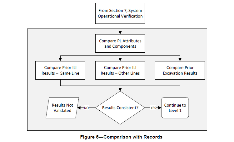
A comparison of pipeline records, for example, ensuring that all hard points were identified in the inline inspection report, isn’t necessarily a new requirement. Still, it’s more clearly defined in the 3rd Edition. This involves reviewing the inline inspection report and comparing it to any available pipeline information to ensure that diameter, mainline valves, bends, and wall thickness changes, for example, are correctly reported. A comparison of the ILI to pipeline records, “and at least one of the other steps is required for all validations,” as seen in the following Figure 5 from 3rd Edition.

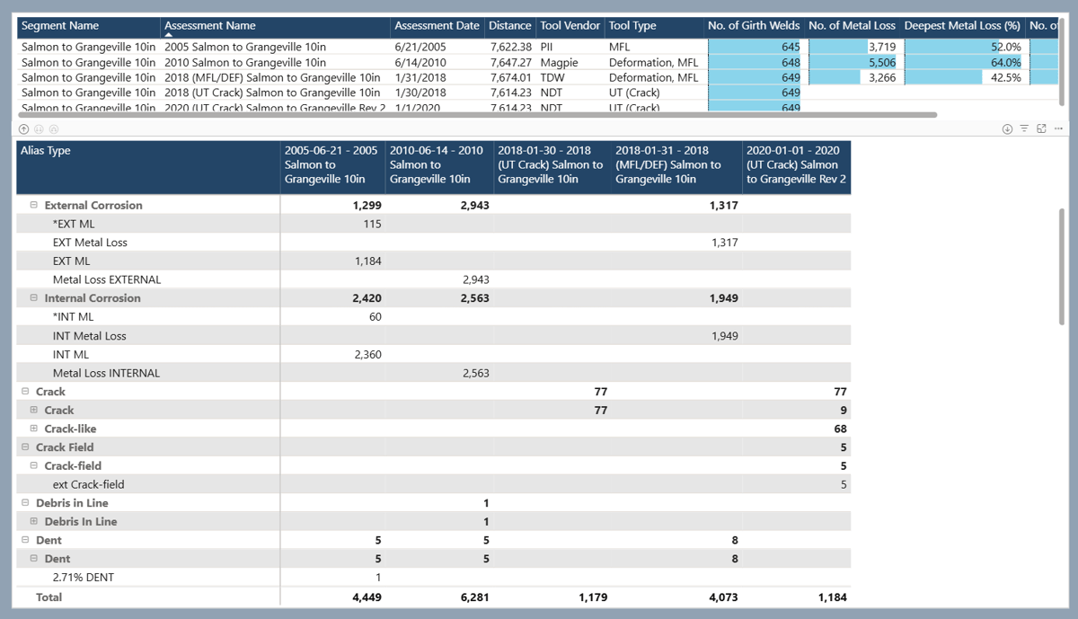
A records comparison can be supported by multiple reports in Asset Integrity for Pipelines (AIP, formerly CIM), as seen in the following figures.

Level 1 Validation - New Implementation Options
Although Figure 5 is entitled “Comparison with Records,” it discusses the different Level 1 validation methods.
Option 1. Compare Prior Excavation Results - ILI to Previously Recoated Anomalies (Section 8.2.2.5)
The comparison points are the depths of previously recoated anomalies that are matched to anomalies in the current ILI. The depth comparison can be plotted on a unity plot, and the fraction of points (p hat) within the tolerance bands is compared to the certainty, e.g., 80%.
The fraction of points (p hat) = X / n, where X = number of measurements within tolerance, e.g., +/- 10%, and n = number of measurements.
The following shows a Level 1 - Option 1 analysis in AIP, also known as a Metal Loss (Historical) Unity plot. Depths from the current ILI are automatically matched to depths of previously repaired anomalies.

This option can be achieved by conducting a Level 2 analysis utilizing the PRCI Guidance spreadsheet.
Option 2. Compare Prior ILI Results - ILI to ILI
(Section 8.2.2.3; the title for this section in the 3rd Edition is considered a typo.)
The comparison points are the depths of anomalies in the previous ILI matched to anomalies in the current ILI. Similar to Option 1, the depth comparison can be plotted on a unity plot, and the fraction of points (p hat) within the tolerance bands is compared to the certainty, e.g., 80%. For this option, a combined tolerance can be used per the 3rd edition. However, “using a combined tolerance increases the upper and lower confidence bound, making this approach a weaker validation.” Figure 7 from the 3rd Edition below shows a unity plot comparing the depths of anomalies from the current ILI versus a previous ILI.

This option can be achieved by conducting a Level 2 analysis utilizing the PRCI Guidance spreadsheet.
Option 3. Compare Prior ILI Results – Validated Inspection on Similar Line
(Section 8.2.2.4)
If an inline inspection system has been validated on a similar pipeline, it can be considered validated under this option. Additional information on implementing Option 3 is provided in the PRCI guidance document, including instructions on identifying “similar pipelines” (Section 4.3.3) and utilizing prior information (Section 4.7).
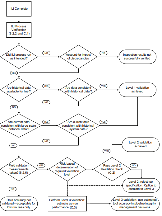
Level 2 Validation: 4 Outcomes vs. 2
The Level 2 calculation in the 3rd edition includes a two-sided binomial confidence interval, where both the upper and lower endpoints are calculated. Instead of two results, “reject” and “not reject”, there are three outcomes. When considering the lower confidence interval endpoint threshold, there are, in fact, four outcomes, as shown in Figure 8b from the 3rd Edition below.

Applying API 1163 3rd Edition: Real-World Help
If the 3rd Edition of API 1163 serves as the framework, the PRCI Guidance Document serves as the how-to manual. It expands on key concepts like:
- How to implement each of the three levels of validation
- Comparing ILI data to prior ILI runs or field measurements
- Defining “similar pipelines” and when it’s appropriate to use cross-line comparisons
- Calculating confidence intervals and tolerance bounds with spreadsheet tools
Better yet, the PRCI spreadsheet tool standardizes these methods in a way that ILI vendors recognize and support, reducing the friction between operators and service providers. PRCI has done the math for you, taking the guesswork out of determining the minimum number of validation points (6 for a Level 2 and 10 for a Level 3) and confidence levels, for example.
Implementing a Level 2 and Level 3 analysis has never been easier with the PRCI spreadsheet, which has been built into Asset Integrity for Pipelines (formerly CIM).
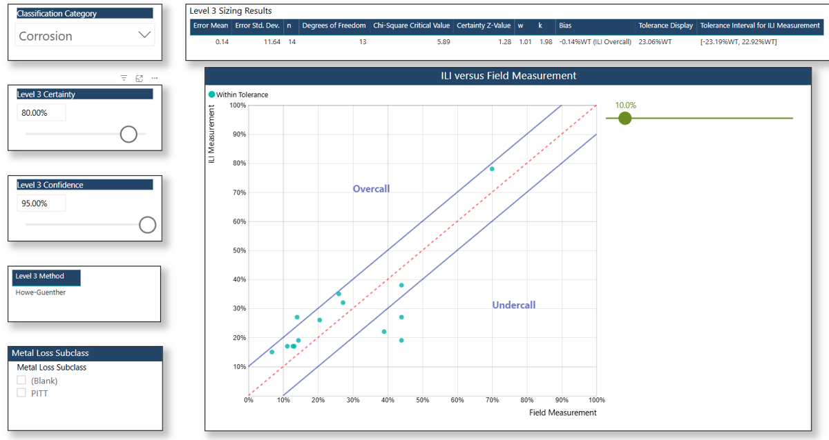
A Level 3 provides more useful results than a Level 2, as it provides the calculated ILI measurement bias and tolerance.
Want the full 25-page comparison of API 1163 3rd Edition versus 2nd Edition?